Published On Feb 10, 2020
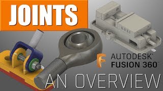
In this video, we’re going to use Fusion 360’s joint simulation ability to simulate the movement of a ninety degree gear joint!
FULL FUSION 360 JOINT TUTORIAL PLAYLIST
• Creating MOVING HINGE JOINTS in Autod...
First things first – I’m really not trying to create a super accurate gear model, meaning a gear that’s exactly mathematically correct, but rather focusing on simulating the movement. This should get you close enough to create a visual approximation, and might even work if you were to 3D print the gears, but I have not gone through and done the calculations necessary to make this an exact mathematical gear model.
Download gears from the McMaster Carr Library
Place gears using the move tool
Note this doesn’t have to be perfect for this application – just get close
These gears are going to be built as as-built joints, or joints that are modeled in place, rather than normal joints, which move relative to each other
Create an empty component, then put a sketch line inside the component. This will act as your ground component
Create an as-built revolute joint between the sketch line and the gear
Ground the sketch line component
Do the same thing for the second gear
Now, create a motion link between the two gears – the smaller gear should have a gear ratio half that of the larger gear