Published On Mar 22, 2022
Inside Wireless is RF elements short, educative video series on topics from the world of RF engineering. In this episode we talk about antenna arrays.
Antennas are all around us these days, but what is an antenna array? In cases when the radiation pattern of a single antenna is too wide, or if its gain is low, antenna arrays come handy. Antenna array is typically a setup of two or more identical antennas working as one by being fed the same signal simultaneously.
Check our Horn antenna technology for 5 GHz unlicensed WISP networks:
http://rfelements.com/products
Forming an antenna array has two main effects, compared to a single antenna by itself, an array has:
1. Radiation pattern with one main beam and side lobes
2. Higher resulting gain of the main lobe.
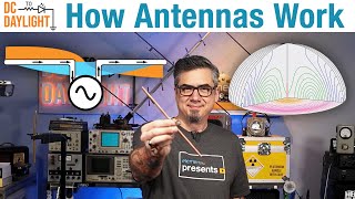
This gives antenna engineers the freedom to tweak the gain and radiation pattern as needed. How does it work? Looking at the fields of an array of two patch antennas vs. one patch, there is a clear difference. There are directions where the fields are strong and in other directions, they are weak. This is caused by wave interference. The maxima come from constructive interference when the waves from both patches have the same phase adding together resulting in a stronger wave. The minima come from destructive interference where the waves have an opposite phase canceling each other out. The maxima and minima correspond to the lobes and nulls in the far field radiation pattern.
The more antennas in an array, the higher the resulting gain of the main lobe. At the same time, the beam width of the main lobe is decreasing. The weaker beams aimed in different directions than the main lobe are called side lobes and are generally undesired and shrink with the array size.
This principle is universal regardless of what is the basic radiating element - using patch antenna, parabolic dish, or a horn will result in a radiation pattern with similar main features - the main beam and sidelobes.
The spacing between the array elements determines the beamwidth of the main lobe - the further apart they are, the larger the physical size of the array effectively decreasing the beam width. Also the angles and size of the side lobes change with element spacing because the fields add up differently for different antenna spacing.
Arrays can be linear - resulting in a changing radiation pattern along the array axis; Surface, resulting in changing radiation pattern along both axes, or conformal to fit various surfaces of devices or larger systems.
Most common example of an antenna array is a Patch array, where a number of patches is etched on a printed circuit board and fed through a symmetrical feeding network. Patch arrays are used in many applications such as cellular network coverage, radars, or airplanes due to the flexibility and affordability of the technology.
Check other Inside Wireless episodes here: • Inside Wireless: Path Loss
Learn more: https://rfelements.com/
0:00 - Intro
0:19 - Definition & Benefits
0:52 - Wave interference
1:29 - Increasing number of elements
1:59 - Element spacing effect
2:17 - Array examples & Applications
#RFelements #InsideWireless #AntennaArray #Antennas #AntennaTheory #WISP #SaveSpectrum #RejectNoise #growsmart #UbiquitiNetworks #CambiumNetworks #MimosaNetworks #Mikrotik