Published On Oct 17, 2020
To Watch this video in Urdu / Hindi • #83 Switch Mode Power Supply Circuit ...
in this video i explained circuit explanation of Switch Mode Power Supply Circuit using SW2604 SMPS Controller.
SW2604 bipolar process, the built-in anti-overload, anti-saturation circuit, to meet the green standard switching power supply controller; to improve Consistency circuit performance parameters, the internal reference voltage specially designed to improve the accuracy of the internal reference voltage. With wide power supply (85–265) design, typical output power of 12W, the maximum output power up to 15W, the peak output power of 18W. Widely used in economical switching power supply, Such as DVD, set-top boxes, fax machines, printers, LCD displays.
Features
1. Built-in anti-overload, saturation circuit, in time to prevent an overload, switch transformer saturation and output short circuit fault
2. adopt 700V voltage bipolar transistor as a switch; while taking advantage of its amplification to complete the start, and power consumption is reduced startup resistor More than 10 times
3. switch built-in, reduce costs, improve the circuit cost
4. built-in slope compensation circuit, thermal protection circuit, the slope current drive circuit
5. Built-in thermal protection circuit
6. Low start-up and operating current
7. VCC overvoltage automatically limits
8. No output power consumption less than 0.15W
9. minimal external components10. Package: DIP8
Definition of electrical parameters:
Start-up receiving current: the current at point OE when the OB starts to have a 0.1mA pull-down current during the startup phase.
Startup quiescent current: VCC connects to filter capacitor and adjustable current source, CT connects to 820PF, and other pins are left floating to enable VCC
The minimum current source current during oscillation (that is, that can complete the startup of SW2604).
Start-up voltage: The maximum VCC value of the above-mentioned VCC oscillation.
Restart voltage: the minimum VCC value of the above-mentioned VCC oscillation.
Oscillator shutdown voltage: The VCC value at which the above-mentioned falling edge of VCC oscillation stops the oscillator.
Quiescent current: In the normal phase, FB is grounded by a 1.8K resistor and VCC power supply current.
Oscillator pull-up/pull-down current: normal phase, FB=2.5V, CT=1.25V, pull-up/pull-down current at CT.
FB pull-up current: in normal phase, FB=2.5V, IS=0V, FB pull-up current.
FB upper limit current prevention: normal phase, FB=2.5V, IS=0.8V, pull-down current at FB.
Internal feedback power supply voltage: SW2604 power supply without external standby feedback circuit, VCC value in normal phase.
IS upper limit voltage: FB=2.5V, add an adjustable power supply to IS, the minimum IS voltage with pull-down current at FB.
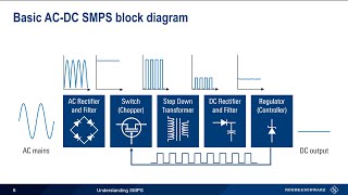
1 basic working concept of smps switch mode power supply
2. how PWM pulse width modulator work
3. circuit diagram of #smps switch mode power supply mobile battery charger
4. practical circuit tracing of #smps mobile battery charger
5 how to repair mobile charger
6 different faults in stages of smps
7. what is optocoupler or opto-isolator and what is its function in #feedback circuit
8 what is voltage regulation and how it workks in SMPS
and much more
switch mode power supply,switch mode power supply circuit diagram,sw2604,sw2604a,smps controller ic,smps pwm controller ic,pwm controller circuit diagram,smps tutorial,smps tutorial 2,smps tutorial in hindi,smps repair,switch mode power supply repair,switch mode power supply tutorial,switch mode power supply explained,haseeb electronics,smps function,smps functions and operations,smps parts and function,how to design switch,how to design switch mode power supply