Published On May 25, 2024
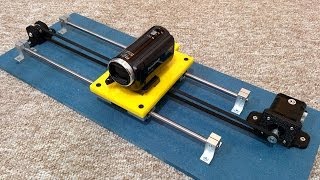
In this video, we will show you step-by-step how to create a DIY linear actuator using 4040 V-Slot extrusion. This is an easy to build, powerful, and fast linear actuator using Openbuilds 4040 Vslot and an Igus High Helix 1/4" Leadscrew. We'll look at the parts, do a quick overview of how it works, and then do the build. At the end there's a short vid of it running.
Bill of Materials:
https://github.com/MikesMachines/VCyl...
00:00 Start
02:28 The Igus and Openbuilds magic (if nothing else, see this part)
09:45 Tube, screw, nut going into the vslot
13:29 Running
I did not expect to build such a compact machine - it just worked out like that. The screw (300mm here) is a bit too long for the 175mm of vslot.
This mostly uses off the shelf components. If you are comfortable working with aluminum (cutting, drilling, tapping) you should be able to build this in a couple hours.
I could see selling this without the motor / electronics in various stroke lengths.
Parts:
4040 V-Slot from Openbuilds
Igus 1/4" High Helix Lead screw with 1" lead.
Igus High Helix lead screw nut, square flange
18mm OD / 12mm ID aluminum tube
Sizing info:
1. For light duty, the vslot needs to be about 2" longer than the desired stroke. As the tube reaches the end of the stroke, there is less vslot covering and stabilizing the tube.
2. The tube should extend about 2" from the end of the vslot when fully retracted.
3. The screw should be close to the same size of the vslot, plus the length needed to extend through the pulley. The screw needs to stop about an inch from the end of the tube (or more) to allow for the internal threads.
Printed parts (in progress):
https://www.thingiverse.com/thing:663...
Notes:
1. The screw is very soft. This is true for the 10x50mm screw also. Set screws will damage the threads. The nut can be damaged going over damaged threads.
2. I usually make a notch with a dremel for o-rings around the end support spacer. This stops any movement around the spacer while still allowing it to spin.
3. One overall issue is the non-metric screw. Everything else is metric. I'd prefer to use steel bearings / bushings, but the sizes needed don't seem available.
Future improvements:
1. Sizing the vslot, tube and screw lengths correctly.
2. 1/4" thrust bearings inside the lock collars
3. Using a bearing in place of the piece of tube support - or some way of integrating a bearing into the end cap.
4. Milling some aluminum in place of the printed pieces (could make a bearing support in the cap)
5. Cover for pulleys - clear polycarb might work well.
6. All the final touches - foam for noise reduction, thread locker to stop nut and bolts rattling
7. Have an option for the motor to be inline - remove the pulleys and belt. The only benefit to the belt setup is reducing the overall length. The drawback is the complexity and reduced force.
Sorry about the captions - I thought they were just exported to a file, not part of the actual video! If you have CC turned on, you'll see double captions