Published On Jan 7, 2022
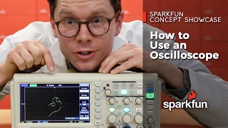
in this video i demonstrated How To Test Signal With Oscilloscope /How to Connect DSO to Test Signal. to set DSO to test signal using DSO digital storage oscilloscope or CRO cathode ray Oscilloscope, we must use attenuation option on the probe for safety, specially when we are testing some hing amplitude signak. the oscilloscope probe have 1x attenuation setting to apply test signal directly to the oscilloscope, while at 10x setting the probe attenuates the test signal by 10 times so the oscilloscope will receive a reduced amplitude level signal.
coupling option is to connect test signal to the dso sampling circuit.
dc coupling. in this setting the test signal is passed through a dc filter and oscilloscope displays the signal directly as it is at test point after processing through its processing circuit
ac coupling. in this option the dc component in the test signal is blocked and just ac signal is allowed to pass to the processing circuit, because in this option the DSO uses a capacitive filter circuit,
ground coupling. in this option the dso sampling circuit is connected to the ground so that the oscilloscope will not display any signal and the display bar will set to its present position
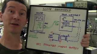
to connect to any signal, always find the signal return path to measure the signal properly, connect oscilloscope ground must be connected to the signal ground, and connect the test probe to the test point
in this tutorial i demonstrated how to use dso or cro to any test point to measure voltage, frequency