Published On Aug 8, 2021
#fire #damper #installation #training #tectonic #work
Warning: The wiring technician must have training and experience
With electronic circuits. Turn off the power before trying anything
Wiring connections or modifications. Make all connections compliant
Follow all local and national codes with wiring diagrams and compatibility.
Provide disconnection and overload protection if necessary. Use copper,
Twisted pair, conductors only. If using the power line, connect
Flu to the actuator should be done with exhilarating condit.
Always read the controller manufacturer's installation
Careful literature before making any connection. Follow all
Instructions in this literature. you have any questions.
please get in touch
Controller manufacturer and / or Belimo.
Transformer (s)
Belimo Actuators require a 24 VAC Class 2 transformer. The
The actuator plug cannot be opened at the fee, no
Parts or components must be replaced or repaired.
EMC Order: 2004/108 / EC
Software Class A: Type 1 operating system
Low voltage order: 2006/95 / EC
Example: 3 AF actuators provided, 16 Ga. Wire (see table
Page 3)
350 feet
Warning: It is good practice to operate electronic or digital controllers
From a separate transformer rather than using actuators or other
Final devices. Power supply design for our actuators and other terminals
Devices use a half-wave rectify cation. Some controllers use full wave
Correction. When there are two types of electricity
Connected to the same power transformer and DC Commons
Connected together, a shortcut is formed in one of the diodes
Full wave power, will damage the controller. Use only a single one
If Power is known to the Power Transformer Controller and Actuator
The controller power uses a half-wave rectify cation.
Multiple drives, one transformer
Multiple actuators can be operated from a single transformer provided
The following rules are followed:
1. The total current draw (VA rating) of the actuators is or less
Equal to the rating of the transformer.
2. The polarity on the secondary of the transformer is strictly adhered to.
This means that all the No. 1 wires from all the actuators are connected
Transformer and all No. 2 wires on all common legs
The actuators are connected to the hotlock. Mixing wire number 1 & 2 on one
The foot of the transformer can cause irregular operation or malfunction
Actuator and / or controls.
Many drivers, many transformers
Multiple actuators can be operated by a single control signal
The following rules are followed from many supplied transformers:
1. The transformers are in the correct size.
2. All No. 1 wires from all actuators are tied together and tied together
Negative leg of the control signal. See wiring diagram.
Wire Type and Wire Installation Tips
For most installations, 18 or 16 ka. The cable works well with Belimo
Drivers. Review job requirements and determine whether a plenum
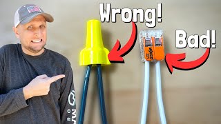
Or device rated cable is appropriate. Use code-approved wire nuts,
Wire connected terminal strips or non-solder connectors. This
Good practice to run unrestricted wires from the actuator
If the controller pieces are unavoidable, make sure there is a split
Achieved for possible maintenance. Split the tape and / or wire
Minimize the chance of the split being inadvertently pulled.
Wire length for actuator installation
The power cord runs below the lengths listed in the following table.
If more than one actuator is operated from the same wire run, disconnect
Allowed wire length by number of actuators to determine
Maximum run for any single actuator.